19. Porous Media#
A porous screen or solid matrix resists fluid motion. When its pores are not resolved by the grid, this resistance is represented by a force in the momentum equation. The matrix is stationary; its resistance may be isotropic or depend on direction.
The resistance model below adds this force to the fluid equations. The local thermal equilibrium model also accounts for fluid volume fraction and heat stored in the matrix.
19.1. Resistance Law#
The momentum equation with porous resistance is
Here \(\vec S_b\) contains other body forces and \(\vec S_p\) is the porous force per unit volume. The bulk, or superficial, velocity \(\vec u\) is based on the total flow area, including the solid fraction. The resistance coefficients must use this velocity convention.
An isotropic resistance acts opposite to the velocity:
The coefficient \(C\) has units of \(\mathrm{kg/(m^3\,s)}\). The force removes kinetic energy because \(\vec u\cdot\vec S_p=-C\lVert\vec u\rVert^2\leq0\). A Darcy–Forchheimer law combines viscous and inertial drag:
The viscous coefficient \(d=1/K\) is inverse permeability and has units of inverse area. The inertial coefficient \(f\) has units of inverse length. Both are nonnegative. In the alternative convention \(C=\mu/K+\rho\beta_{\mathrm F}\lVert\vec u\rVert\), the same law has \(f=2\beta_{\mathrm F}\).
For steady one-dimensional flow with constant velocity \(U\) and coefficient \(C\), pressure balances drag when \(dp/dx=-CU\). Across a layer of thickness \(L\), the Darcy–Forchheimer law gives
The positions \(0\) and \(L\) remain fixed when flow reverses. Thus the pressure difference changes sign with \(U\).
19.1.1. Directional Resistance#
For an anisotropic material, replace the scalar coefficient by a tensor:
The coefficients \(d_i\) and \(f_i\) specify viscous and inertial resistance along three mutually perpendicular material axes. With these unit axes as columns of \(\Matrix{Q}\),
Both tensors share the same material axes. The \(d_i\) have units of inverse area and the \(f_i\) have units of inverse length. Nonnegative coefficients make \(\Matrix{R}\) symmetric positive semidefinite, so \(\vec u\cdot\vec S_p=-\vec u\cdot\Matrix{R}\vec u\leq0\). The force can change the flow direction while removing kinetic energy. Setting \(d_i=d\) and \(f_i=f\) gives the isotropic limit \(\Matrix{R}=C\Matrix{I}\), where \(\Matrix{I}\) is the identity tensor.
19.1.2. Screen Correlations#
Screen correlations specify the scalar coefficient \(C\) through empirical parameters. The Armour–Cannon–Cady (ACC) correlation gives [AC68, Cad73]
Here \(\epsilon\) is void fraction, \(a_v\) is screen surface area per unit volume, \(D_p\) is hydraulic pore diameter, and \(Q_{\mathrm{ACC}}\) is a tortuosity factor. The constants \(\alpha_{\mathrm{ACC}}\) and \(\beta_{\mathrm{ACC}}\) set the viscous and inertial resistance. The ratio \(B/B_{\mathrm{CFD}}\) accounts for the physical screen thickness relative to the thickness of the modeled region.
The numerically determined resistance (NDR) correlation retains only quadratic drag:
The fitted coefficient \(K_q\) has units of inverse length. Both correlations require parameters that give \(C\geq0\) and a positive void fraction.
19.2. Force on a Control Volume#
Following the momentum-interpolation chapter, denote the integrated body force by \(\vec{\mathcal B}\). The porous contribution in cell \(P\) is
19.2.1. Cell-Centered Approximation#
Evaluating the force at the cell center gives
For isotropic resistance, this becomes \(\vec{\mathcal B}_{p,P}^{\mathrm{std}}=-{}^{(u)}\!a_{P,\mathrm{por}}\vec u_P\), where \({}^{(u)}\!a_{P,\mathrm{por}}=C_P\Omega_P\). The nonnegative scalar coefficient, or its tensor counterpart \(\Omega_P\Matrix{R}_P\), can be added to the momentum diagonal.
19.2.2. Conservative Face Assembly#
Consider an internal face with \(P\) on its stored left side and \(N\) on its right. The area vector \(\vec A_f=A_f\hat{\vec n}_f\) points from \(P\) to \(N\). Approximate the force as constant on each segment from the cell center to the face center. Its line integral is
This is the line estimate defined in Eq. (5.7.1.2). It has pressure units and estimates \(p_N-p_P\) when pressure balances resistance along the path.
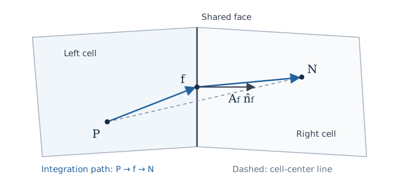
Fig. 19.2.2.1 The two segments used to estimate the pressure change due to resistance. The face center need not lie on the line joining the cell centers.#
Use the distance weights from Eq. (5.4.1.11):
Ordinary interpolation is \(\mathcal I_f(q)=w_Pq_P+w_Nq_N\). For force assembly, multiply the pressure change by \(\vec A_f\) and distribute it in proportion to each cell’s segment length:
Cell \(P\) receives the fraction \(w_N\), which measures its own segment length. These weights therefore appear in the opposite order to ordinary interpolation. The shares sum to the entire force \(L_f(\vec S_p)\vec A_f\). Reversing the stored orientation reverses both \(L_f\) and \(\vec A_f\), leaving their product unchanged. Conversion to a cell-outward orientation likewise introduces two incidence signs, which cancel.
At a physical boundary, use the segment from the owner cell to the face and the outward area vector:
Sum the contributions over the cell’s faces to obtain \(\vec{\mathcal B}_{p,P}^{\mathrm c}\). On a skewed mesh or across a change in resistance, this assembled force need not be parallel to \(-\vec u_P\), even for an isotropic material.
19.3. Explicit and Implicit Treatment#
At outer iteration \(k\), evaluate the resistance tensor and integrated force from the current state. For isotropic resistance, use \(\Matrix{R}=C\Matrix{I}\). With an explicit porous source, the unrelaxed predictor equation is
The diagonal \({}^{(u)}\!a_{P,0}\) includes transport and time-discretization terms but excludes porous resistance. The known vector \({}^{(u)}\!\vec b_{P,0}\) excludes porous force and the integrated pressure term \(\vec{\mathcal P}_P\), both written separately. The star denotes provisional velocity. Coefficients are fixed during this solve; their iteration labels are suppressed. Either spatial assembly supplies \(\vec{\mathcal B}_{p,P}\).
For implicit treatment, hold \(\Matrix{R}_P\) fixed and write
Substitute this split into the predictor equation and move the term proportional to \(\vec u_P^*\) to the left. The local momentum diagonal is
The implicit row becomes
In the isotropic limit, \(\Matrix{A}_P={}^{(u)}\!a_P\Matrix{I}\) with \({}^{(u)}\!a_P={}^{(u)}\!a_{P,0}+{}^{(u)}\!a_{P,\mathrm{por}}\). The remainder \(\vec{\mathcal B}_{p,P}^{\,\mathrm{rhs},k}\) is zero for the cell-centered force. For conservative assembly, it retains the part of the assembled force not represented by the local implicit term. At convergence, \(\vec u_P^*=\vec u_P^k\), so the split recovers the complete force.
This Picard linearization updates the speed-dependent resistance at each outer iteration. Adding resistance to the diagonal reduces the lagged feedback that can make explicit treatment converge poorly at high resistance.
For velocity under-relaxation \(0<\alpha_v\leq1\) applied to the complete diagonal, the relaxed diagonal is \(\Matrix{A}_P/\alpha_v\). The SIMPLE velocity correction holds these coefficients fixed and neglects neighbor-velocity corrections. An integrated pressure change \(\vec{\mathcal P}'_P\) then gives
The same inverse must weight pressure and force in the face flux.
19.4. Face Flux and Pressure Correction#
Let \(\vec r_{PN}=\vec x_N-\vec x_P\) and \(\ell_f=\vec r_{PN}\cdot\hat{\vec n}_f>0\). With \(\vec S_b=0\), classical momentum interpolation with relaxation of the complete diagonal gives
The corrections \(\mathcal C_{p,f}^{\mathrm{int}}\) and \(\Delta\dot\Omega_{p,f}\) replace the pressure and porous-force contributions carried by the interpolated cell velocities. The last term preserves the relaxation history, as in Classical Rhie–Chow Form and Under-Relaxation.
19.4.1. Isotropic Face Flux#
On an orthogonal face, the direct source is \(L_f(\vec S_p)/\ell_f\). Weight it by the same coefficient as the direct pressure gradient and subtract the interpolated cell-force contribution:
Here \({}^{(u)}\!a_P\) is the complete unrelaxed diagonal: \({}^{(u)}\!a_{P,0}\) for explicit treatment and \({}^{(u)}\!a_{P,0}+{}^{(u)}\!a_{P,\mathrm{por}}\) for implicit treatment.
Important
The face balance uses the physical force \(\vec{\mathcal B}_{p,P}\). The remainder \(\vec{\mathcal B}_{p,P}^{\mathrm{rhs}}\) belongs to the linearized momentum right-hand side; it does not replace the physical force in this correction.
Add the integrated-pressure correction from Eq. (5.7.1.5), with the same diagonal:
The first term vanishes when pressure and porous force balance in each cell. The second vanishes when the pressure difference equals the line estimate. Both conditions are needed to preserve this balance at the face.
For time-consistent scalar interpolation, use Eq. (5.7.1.4) with \(\vec S=\vec S_p\) and \(\vec{\mathcal B}=\vec{\mathcal B}_p\). Its spatial diagonal includes any implicit porous resistance; the face denominator and history terms follow the selected interpolation.
19.4.2. Directional Face Flux#
Interpolate the cell inverse from Eq. (19.3.5), including cell volume, to obtain
This averages the inverses of the cell diagonals. A pressure gradient at the face contributes \(-A_f\hat{\vec n}_f\cdot\Matrix{M}_f\nabla p\) to volumetric flux. Separate its coefficient into a part along \(\vec r_{PN}\) and a remainder. Approximate \(\vec r_{PN}\cdot\nabla p\) by \(p_N-p_P\) and evaluate the remainder with the current interpolated gradient:
Holding the cell predictor, source terms, pressure gradient, density, and momentum coefficients fixed, a pressure correction changes mass flux by
For positive density, cell volumes, and \({}^{(u)}\!a_{P,0}\), nonnegative principal resistance coefficients make \(\Matrix{A}_P\) positive definite. With positive interpolation weights and \(\ell_f>0\), this gives \(d_f>0\): increasing \(p_N-p_P\) reduces flux in the stored direction.
Removing the cell pressure contribution and inserting this face estimate gives the pressure term in Eq. (19.4.1):
The last term accounts for directional resistance and mesh nonorthogonality. It is held fixed during pressure correction and updated with the pressure gradient at the next outer iteration.
For the porous force, use the segment weights to form \(\vec S_{p,f}=w_N\vec S_{p,P}+w_P\vec S_{p,N}\). On an orthogonal face, \(\vec S_{p,f}\cdot\hat{\vec n}_f=L_f(\vec S_p)/\ell_f\). On a skewed face, this weighted vector is a separate approximation to the face source. Applying the same tensor coefficient and removing the cell contribution gives
For a constant force and a linear pressure field with \(\nabla p=\vec S_p\), the face terms cancel. If \(\vec{\mathcal P}_P=\vec{\mathcal B}_{p,P}\) in each cell as well, the total pressure–force correction is zero. The isotropic limit on an orthogonal face recovers Eq. (19.4.1.1).
19.5. Time Integration#
Porous force belongs to the spatial momentum residual. Its time weighting and history terms follow the formulas in the time-integration chapter. For constant \(\rho>0\) and \(C>0\), the source-only equation \(\rho\,d\vec u/dt=-C\vec u\) has decay time \(\rho/C\). Thus \(C\Delta t/\rho\) measures how well the time step resolves drag decay. Implicit source treatment improves the nonlinear solve; temporal accuracy still requires resolving the motion of interest.
19.6. Local Thermal Equilibrium#
Local thermal equilibrium (LTE) assumes that the fluid and solid share a temperature \(T\). It applies when heat exchange between them is fast compared with the resolved flow and heating times.
19.6.1. Model and Averaged Quantities#
Consider a rigid, stationary matrix with porosity \(0<\epsilon\leq1\) fixed in time. The fluid has one species, and the flow is laminar. Resistance and thermal conductivity are isotropic; other body forces are omitted.
Let \(\vec v\) be intrinsic fluid velocity, averaged over the pore volume. The superficial velocity is \(\vec u=\epsilon\vec v\). Density \(\rho\) and specific enthalpy \(h\) are intrinsic fluid properties. Thus \(\epsilon\rho\) is fluid mass per total volume, while \(\rho\vec u\) is mass flux per total area. The mass and momentum balances are
The bulk viscous stress is approximated by \(\Matrix{\tau}_b=\epsilon\mu[\nabla\vec v+(\nabla\vec v)^T -\tfrac23(\nabla\cdot\vec v)\Matrix{I}]\). The coefficient \(C=C(\rho,\mu,\lVert\vec u\rVert)\) follows the Darcy–Forchheimer law in Eq. (19.1.3), using superficial velocity.
19.6.2. Combined Fluid–Solid Energy Balance#
For constant solid density \(\rho_s\) and specific heat \(c_s\), the solid heat capacity per total volume is \(C_s=(1-\epsilon)\rho_s c_s\). With a fixed energy reference, its stored energy is \(C_sT\). The fluid total enthalpy and total energy per unit mass are \(H=h+\tfrac12\lVert\vec v\rVert^2\) and \(E=H-p/\rho\). The combined stored energy per total volume is therefore
Heat transferred between fluid and solid enters their energy balances with opposite signs. Adding those balances cancels this internal exchange. The stationary solid stores and conducts energy, while only the fluid advects enthalpy:
Here \(\lambda_{\mathrm{eff}}\) is the combined material conductivity in W/(m K), with heat flux based on total area. The imposed source \(S_{\rho E}\) is heating per total volume in W/m\(^3\); a negative value removes heat. Both quantities already refer to the bulk material and receive no further porosity factor. Drag converts kinetic energy to internal energy within this combined system, so it supplies no additional total-energy source.
Since porosity is fixed in time, moving the pressure derivative to the right gives the total-enthalpy form:
This is one energy equation for the common temperature, expressed through fluid total enthalpy.
19.6.3. Thermodynamic Closure#
At the current pressure and intrinsic velocity, recover temperature from \(h(p,T)=H-\tfrac12\lVert\vec v\rVert^2\), then evaluate \(\rho(p,T)\). Heating and pressure loss change density through this fluid EOS. Porosity weights the fluid inventory; the matrix heat capacity contributes to Eq. (19.6.2.3) without changing the fluid EOS properties.
The fluid specific heat \(c_p=(\partial h/\partial T)_p\) relates temperature and enthalpy changes at fixed pressure. In a sealed, rigid volume at rest, fluid density is instead fixed, and the heat capacity per total volume is \(\epsilon\rho c_v+C_s\), where \(c_v=(\partial e/\partial T)_\rho\). In steady flow with no applied heating, conduction, or viscous work, \(H\) is constant along the flow. A real-fluid EOS can still give a temperature change as pressure falls.
19.6.4. Discrete Enthalpy Equation#
Integrate Eq. (19.6.2.2) over a fixed cell of volume \(\Omega_P\) and approximate its inventory by the cell-center value:
Let \(\mathcal F_{E,f}\) be the total energy flow through face \(f\) in its stored direction. It includes enthalpy transport, conductive heat flow, and viscous work. Backward Euler gives
The incidence sign \(\sigma_{Pf}\) converts each stored face flow to the outward direction for cell \(P\), as defined in Loci Face Orientation and Cell Incidence. In particular, the solid contribution to the storage term is
At outer iteration \(k\), hold pressure and velocity fixed during the enthalpy solve. Linearizing the EOS temperature in \(H\) gives
Substitute this expression into the solid-storage term. Collect the coefficient of \(H_P^{k+1}\) on the left and the known terms on the right:
Let \({}^{(H)}\!a_{P,0}\) and \({}^{(H)}\!b_{P,0}\) contain all other terms, including porosity-weighted fluid storage, transport, pressure work, and applied heating. The enthalpy row becomes
Enthalpy Row
The EOS temperature and \(c_p\) are updated between outer iterations. At convergence, the added terms recover the solid energy change in Eq. (19.6.4.3).
19.6.5. Heat Conduction Between Cells#
Consider an orthogonal face with cell \(P\) on its stored left side and \(N\) on its right. Let \(\ell_P\) and \(\ell_N\) be the center-to-face distances, and let \(\lambda_P\) and \(\lambda_N\) denote the effective conductivities. Assuming perfect thermal contact at the face and constant conductivity on each segment, the two thermal resistances add. The conductive heat flow, positive from \(P\) to \(N\), is
The interface temperature is continuous, while its normal gradient changes to carry the same heat flow through both materials. If either conductivity is zero, the series resistance gives zero heat flow. For a nonorthogonal face, use the temperature-gradient correction in Eq. (4.2.1.16), with face conductivity obtained from the same two segment resistances.
The full face energy flow in Eq. (19.6.4.2) is
Each internal face has one flow rate and opposite incidence signs in its two cell balances, so its contributions cancel when those balances are summed.
19.6.6. Pressure and Velocity Coupling#
All convected quantities use the same mass flow \(\dot m_f\). Interpolate \(\epsilon\vec v\) to form the cell part of the superficial face velocity. For SIMPLE, hold the momentum coefficients fixed and neglect neighboring velocity corrections. The integrated pressure force then gives
Here \({}^{(v)}\!a_P\) is the complete unrelaxed momentum diagonal, including the drag contribution \(\epsilon_P^2 C_P\Omega_P\), and \(\alpha_v\) is velocity relaxation. One porosity factor comes from the pressure force and the other from converting intrinsic to superficial velocity. On an orthogonal face, interpolating this coefficient gives
The center-to-center distance is \(\ell_f=\ell_P+\ell_N\). This expression is the velocity-induced part of the mass-flow correction; density changes also enter the compressible continuity equation.
For the local density correction, hold fluid \(H\) and \(\vec v\) fixed. Then \(dh=0\). With \(\rho_T=(\partial\rho/\partial T)_p\), thermodynamic consistency gives
Thus \(dT/dp=-h_p/c_p\) along this fixed-enthalpy change. Substituting into the density differential gives
This fixed-enthalpy derivative differs from the acoustic derivative in Density-Pressure Linearization In Pressure Correction. It describes the local pressure-correction step; the energy equation and EOS update the thermal state between outer iterations. In backward-Euler continuity, the density correction contributes \(\epsilon_P\Omega_P\rho'_P/\Delta t\) to fluid storage.
At an extrapolated-pressure boundary, include the pressure change associated with drag between the cell center and the face: \(\Delta p_f=-C_P\vec u_P\cdot(\vec x_f-\vec x_P)\). This follows from the local balance \(\nabla p=-C\vec u\) and preserves that balance when porous material reaches a prescribed-flow boundary.
19.7. References#
James C. Armour and Joseph N. Cannon. Fluid flow through woven screens. AIChE Journal, 14(3):415–420, 1968. doi:10.1002/aic.690140315.
E. C. Cady. Study of thermodynamic vent and screen baffle integration for orbital storage and transfer of liquid hydrogen. Technical Report NASA-CR-134482, McDonnell Douglas Astronautics Company, 1973. URL: https://ntrs.nasa.gov/citations/19730025004.